|
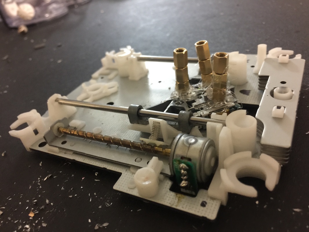
This week, we addressed all of our hardware issues. We solved the uneven build plate by creating a newer and smaller build plate and used hot glue to keep the standoffs on the stepper motor straight. This allowed for the base to be sturdier because the screwed were more stable, and flatter with a smaller plane. Then, we completed all the wiring and connected the printer to the power supply. Now, we have wiring connecting from the stepper motors to the stepper motor drivers, which is in turn connected to our power supply. The stepper drivers are also connected to our USB-powered arduino. Finally, we were able to solder on the disassembled 3D printing pen to our base too! Testing is currently in progress.
0 Comments
With hectic drilling and hot gluing of the printer base, many wires that were flimsily soldered on the week before fell off. The soldering often had metal bubbles, leaving space for the wires to loosely slip off. However, during this meeting, the assembly team had already finished the putting together of the printer base, so the soldering would not have any more handling issues. As a result, the base of the printer is completely finished, allowing for the stepper motor drivers, the Arduino, and the power bank to be finally connected with the printer.
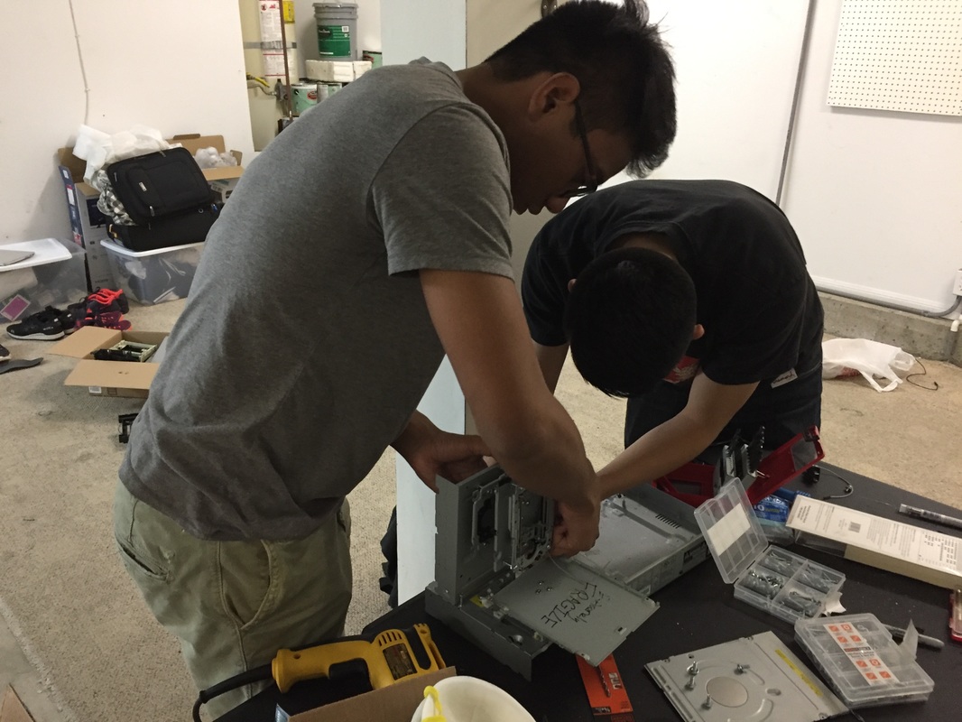
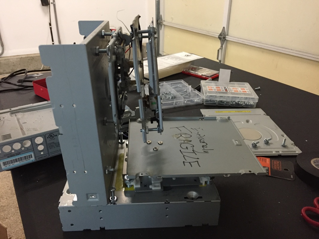
With the last build meeting not only creating an example of what we needed to do but also instilling confidence in our drilling skills, we set out to finish the assembly portion today. With the Y-axis complete, we connected another back of a CD drive perpendicularly to the Y-axis CD drive, securing them with L-braces. Afterwards, we drilled holes in the vertical CD drive back, and connected the Z-axis to that. Because we needed a way for the Z-axis motor to control the X-axis motor also, we ended up choosing the same course of action we did for the Y-axis by also attaching a flat platform on top the Z-axis motor, and then drilling the X-axis motor on top of that platform. As a result, the Z-axis motor moves the X-axis up and down, while the X-axis motor can still move the printing pen forward and backward.
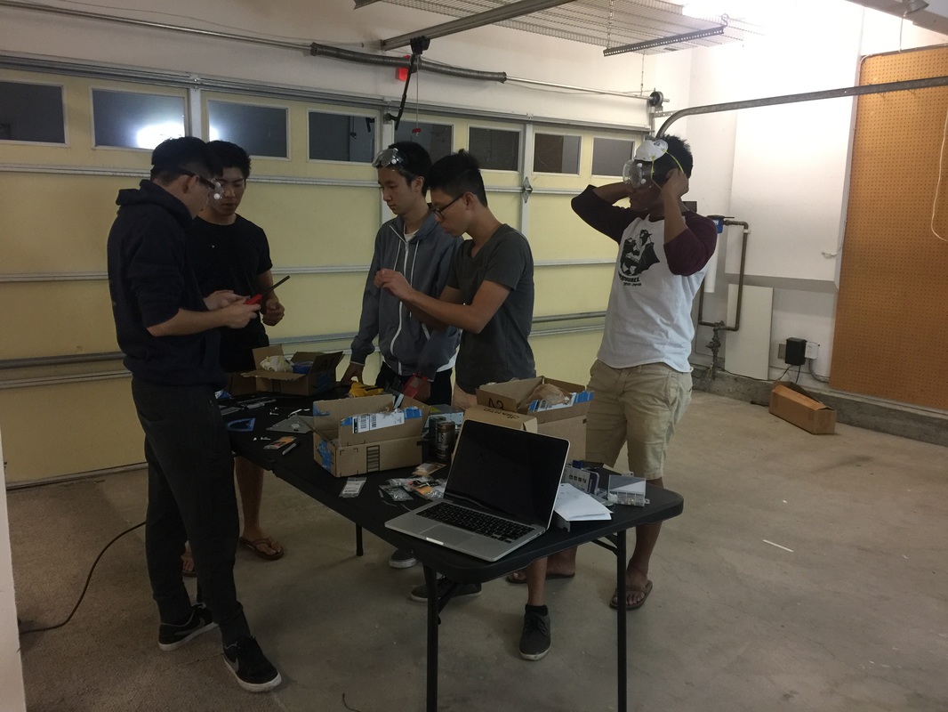
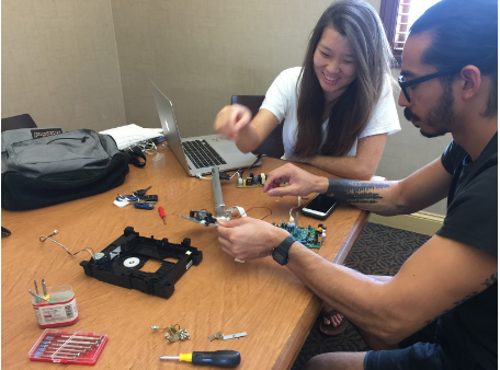
During this meeting, we first designated an area to work on the project safely while being able to have the comfortability and convenience of our own place. Therefore, we chose Alvin's empty garage as an area to do the drilling and soldering. To complete the base of the printer, we first set out to use a drill bit to drill holes through the back of the CD drives and through the stepper motors themselves. This allowed us to place motherboard screws in them both to attach the stepper motor drivers to the old CD drive platforms. Furthermore, after we stabilized and hot glued the motherboard screws so they would stay in place, we drilled holes through a flat piece of metal in order to create a base plate for the bottom stepper motor, which we decided to call the Y-axis motor.
We began the first steps to putting the pieces together! Using a soldering iron and its metal alloy, we attached three wires tipped on each side with copper to each of the three stepper motors in order to be able to connect them to the stepper motor drivers later on. One end is currently attached to the stepper motors while the other will be connected to the arduino, the power supply, and the stepper motor driver. As a result, we will be able to control where they are going, how they are moving, and what powers it to move. These wires are crucial, as they are the missing link that bridges the communication between the drivers, which will be holding the pen and doing the printing, and the rest of the entire project. As a result, this meeting has been useful in drilling the holes and beginning the links to connectivity.
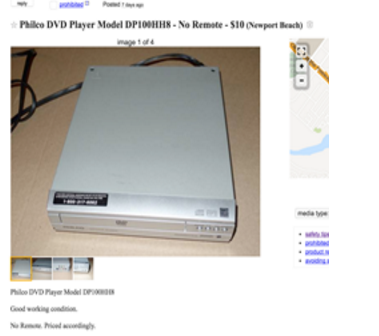
After much anticipation, many of our materials have arrived today. The most fascinating one was the 3D printing pen, with which we used 2 rolls of ABS filament to test out the pen. We immediately ran into some issues regarding the 3D printing pen, like precision of the pen and its print speed. If we were to print a square, the filament does not allow for sharp 90 degree turns. Therefore, we would have to print one side of the square, wait for it to harden, then begin on the next side of the square. We understand that this is time-consuming, but also realize that this is mandatory step to print out more intricate projects. Furthermore, we discovered that the speed at which the 3D pen extrudes the filament varies greatly. If it's too fast, the filament begins to create circles, resulting in swirled designs. If it's too slow, the print would not be substantial enough and break easily. As a result, we would have to experiment with the pen many times to optimize printing speed for meticulous designs.  We then disassembled both the APEX digital and Philco DVD player in order to retrieve the step motor from each drive. Additionally, we separated the outer casing of each DVD player to possible use them as a base and stand. Finally, we found our third DVD player at a cheap price, fulfilling our requirements while still managing our budget wisely.
Together we decided that buying as many DVD players and CD players would be optimal. We wanted to test out different step motors and figured that having too many materials is better than less, considering the cheap cost and our extensive budget. Therefore, we contacted sellers on Craigslist for CD/DVD players to take apart this week and next.
Our first meeting was used to discuss our timelines and begin our research by watching videos and discussing how everything would work together so that software majors could talk to hardware majors and vice versa. Additionally, we decided on project managers and voted based on their qualifications. Finally, we displayed the videos to everyone on the team to ensure everyone was caught up with the entire project.  |